High Shear Mixers A powerful solution for mixing, dispersing and homogenizing materials
Introduction
In the chemical, pharmaceutical, food, cosmetic and paint industries, conventional mixers are not sufficient for mixing materials with different viscosities, breaking lumps, wetting powders and fine droplets. High Shear Mixers enable rapid distribution of materials and the production of uniform emulsions and suspensions by creating high relative speeds and intense shear forces in the mixing zone.
From simple mixing to controlled dispersion
The purpose of this equipment is not simply to rotate materials in a tank; it is to focus high mechanical energy to create shear, turbulence, and effective fluid circulation in processes where product quality depends on particle size and composition stability.
What is a high shear mixer?
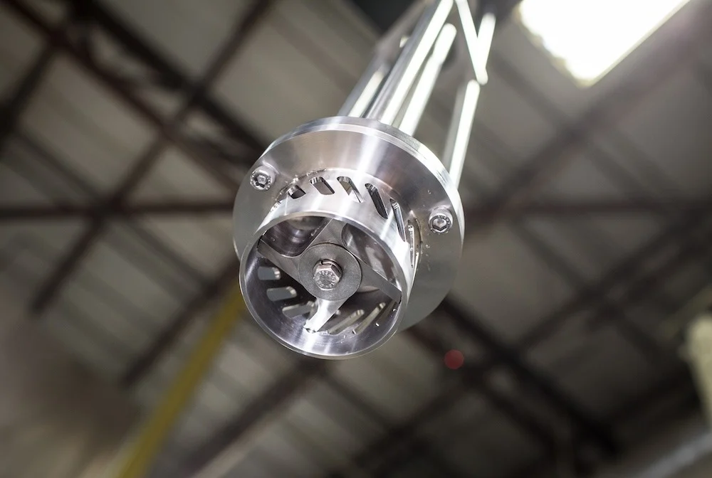
This industrial equipment uses the rapid rotation of the rotor to draw the material into the narrow space between the rotor and the stator and expel it from the stator slots. The resulting shear stress and turbulence make the liquid droplets in the emulsification finer and help disperse powders and reduce agglomerations; however, its selection should be based on the target particle size, viscosity, and capacity and is not a substitute for all high-pressure mills or homogenizers.
Types of device layouts
1. Batch Mixer; Head placed inside the tank to process a specific batch; suitable for producing various products and changing formulations.
2. Inline Mixer; Continuous passage of materials through the rotor-stator chamber; suitable for continuous production lines or tank circulation circuits.
3. Bottom or top-mounted mixer; Head mounted from above, below or in line according to tank design, circulation pattern and maintenance access.
Main components of high shear mixers
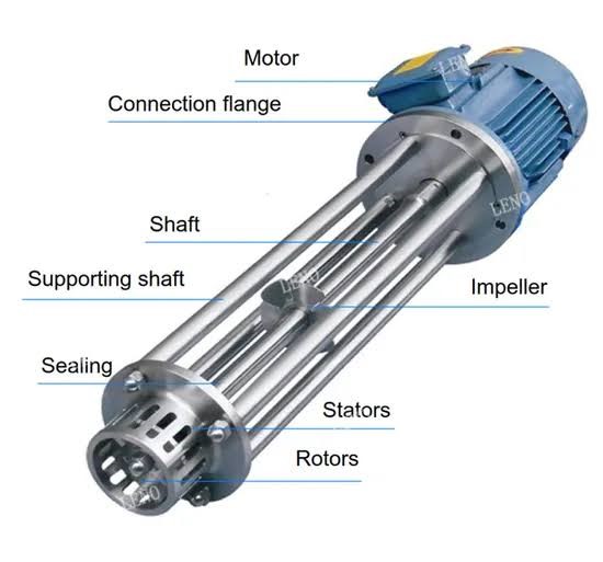
The coordination of the following mechanical and control parts determines the mixing intensity, safety and repeatability of the process:
1. Motor & Gearbox; Providing energy to rotate the shaft and rotor in proportion to the viscosity and batch volume.
2. Shaft & Coupling; Transferring torque to the head with proper alignment and balance to reduce vibration.
3. Rotor; The rotating part of the head at high speed to direct the fluid to the cutting area.
4. Stator; The fixed part around the rotor that divides the flow and creates cutting with its grooves or holes.
5. Mixing Chamber & Tank; A space for storing and circulating materials with a suitable design to prevent dead zones.
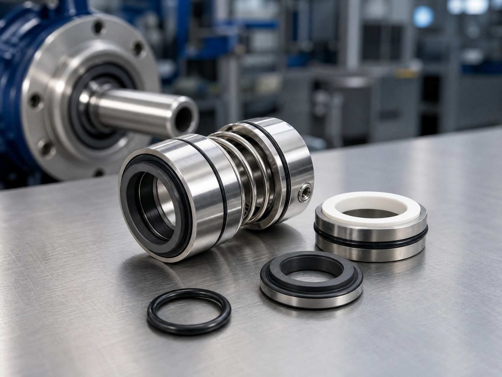
6. Sealing & Bearings; Preventing product leakage and contamination in accordance with temperature, pressure and hygiene requirements.
7. Control System; Monitor and adjust speed, time, temperature and power to improve quality repeatability.
How it works
As the rotor rotates, the suction created draws the material into the narrow gap between the rotor and the stator. After enduring severe shearing, the material returns to the main mass through the stator pores, and repeating this cycle results in uniform and fine droplets or aggregates.
Operating cycle and process parameters
The order of addition of materials, rotor speed, time and temperature is adjusted according to the formulation in five steps:
1. Material preparation; accurate weighing of raw materials and pre-mixing of phases or powders if required.
2. Charging and pre-mixing; gradual addition of materials (especially powders) to the circulating tank to prevent caking and overloading the motor.
3. High shear; repeated passage of materials through the rotor-stator area to disperse, emulsify or break up agglomerations.
4. Temperature and time control; management of heat from mechanical energy with a cooling jacket and time control for heat-sensitive materials.
5. Product completion and discharge; stopping the machine and transferring the product after achieving the desired uniformity, droplet size and viscosity.
Parameters affecting performance
• Tip Speed: An indicator of the intensity of the rotor edge movement (along with other mixing factors).
• Rotor-to-stator distance: Affects shear intensity, pressure drop, and clogging potential.
• Viscosity and material properties: Determine flow pattern, interfacial tension, and power requirements.
• Passage time and number of passes: Needs optimization with process testing to prevent excess heat.
• Tank design and fluid circulation: Essential for placing all product parts in the effective shear zone.
Industrial applications and benefits
High shear mixers are used in processes requiring rapid dispersion, powder wettability and texture uniformity:
• Pharmaceutical industry: Preparation of creams, gels, ointments and suspensions while complying with hygiene requirements.
• Food industry: Production of sauces, mayonnaise, emulsions and stable drinks.
• Cosmetics industry: Production of lotions, shampoos, creams and skin and hair care products.
• Paint and coating industry: Wetting and uniform dispersion of pigments and additives.
• Chemical industry: Production of emulsions, dispersions, adhesives and polymer formulations.
Main benefits
• High mixing and dispersion speed compared to conventional mixers.
• Effective reduction of droplet size and particle agglomerations in accordance with the device design.
• Improved product uniformity and process repeatability by controlling parameters.
• Ability to work in batch and linear arrangements for a variety of formulations.
Maintenance and operating considerations
Periodic inspection of the rotor, stator, shaft, bearings and seals is essential to identify wear, corrosion, vibration or leakage, and repairs should be carried out after de-energizing and safely locking out. In hygienic applications, the chemical compatibility of the surfaces and the ability to be cleaned in place (CIP) or sterilized in place (SIP) must also be considered.
Conclusion
High shear mixers, by concentrating mechanical energy in the rotor and stator assembly, are an efficient solution for industrial dispersing, emulsifying and homogenizing. Proper selection of equipment, control of temperature and process parameters, and proper maintenance ensure consistent product quality and equipment reliability.
Technical Note: Capacity, speed, power, viscosity range and hygiene requirements should be determined based on manufacturer specifications and process testing.